

ZED X One Core Interfaces

Open in ClaudeOpen in ChatGPT

The ZED X One Core exposes all its signals on a single 30-pin Micro I-PEX connector located on the back of the module. This page describes that connector, its voltage levels, its pinout, and the I²C address map of the devices on the board.
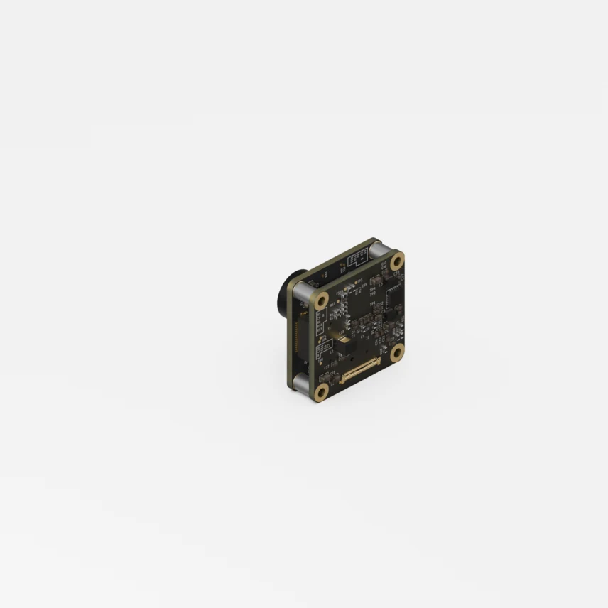
ZED X One Core back side

The information on this page is provided for mechanical and electrical integration purposes. The ZED X One Core is designed for exclusive use with the ZED Link MIPI capture card; connecting it to a third-party host is not supported. If you need to interface the camera with your own carrier board, please contact support@stereolabs.com.

Connector

FeatureValue
Part numberI-PEX 20525-030E-02
Mating connectorFAW-1233-XX
Connector profile30 pins, 0.4 mm pitch
CableMIPI Micro I-PEX, up to 50 cm

Signal voltage levels

PinsGroupLevel
1 - 4, 6 - 11MIPI CSI-2 data lanes (D0-D3) and clockMIPI D-PHY signaling (1.2 V nominal)
12 - 21Control, sync and interrupts (FSIN, I²C, S_RST, FLASH_EN, INT1/2/4)1.8 V CMOS
28 - 30VDD_3V3 supply3.3 V
5, 22 - 27Ground / Not connected-

Pin description

PinNameLevelDir.Function
1MIPI_D3PD-PHY 1.2 VOutCSI-2 data lane 3 (+)
2MIPI_D3ND-PHY 1.2 VOutCSI-2 data lane 3 (-)
3MIPI_D1PD-PHY 1.2 VOutCSI-2 data lane 1 (+)
4MIPI_D1ND-PHY 1.2 VOutCSI-2 data lane 1 (-)
5GND--Ground reference
6MIPI_CPD-PHY 1.2 VOutCSI-2 clock lane (+)
7MIPI_CND-PHY 1.2 VOutCSI-2 clock lane (-)
8MIPI_D0PD-PHY 1.2 VOutCSI-2 data lane 0 (+)
9MIPI_D0ND-PHY 1.2 VOutCSI-2 data lane 0 (-)
10MIPI_D2PD-PHY 1.2 VOutCSI-2 data lane 2 (+)
11MIPI_D2ND-PHY 1.2 VOutCSI-2 data lane 2 (-)
12FSIN1.8 VInFrame-sync / external trigger input, used for multi-camera synchronization
13S_SCL1.8 VIn (OD)I²C clock, camera control bus, the host is the master
14S_SDA1.8 VBi-Dir. (OD)I²C data
15S_RST1.8 VInSensor reset
16NC--Not connected, do not drive
17FLASH_EN1.8 VOutControl signal to drive external light sources
18NC--Not connected, do not drive
19INT11.8 VOutIMU interrupt, BMI088 accelerometer INT1
20INT21.8 VOutIMU interrupt, BMI088 accelerometer INT2 (internally connected to INT4)
21INT41.8 VOutIMU interrupt, BMI088 gyroscope INT4 (internally connected to INT2)
22-27NC--Not connected, do not drive
28-30VDD_3V33.3 VPower In3.3 V supply input, three pins in parallel for current capacity

Pins 28 to 30 must all be connected: they carry the 3.3 V supply in parallel to provide the required current capacity. The module draws 0.8 W (240 mA @ 3.3 VDC).

Multi-camera synchronization

The FSIN input (pin 12) is the frame-sync / external trigger signal. When several ZED X One Core cameras are driven from the same trigger source, their exposures are aligned at frame level with a precision of 15 µs, which is what makes multi-camera surround vision and stereo pairs usable for perception.

I²C address map

Address (7-bit)Device
0x10AR0234 image sensor
0x19BMI088 IMU - accelerometer
0x69BMI088 IMU - gyroscope
0x54EEPROM
0x56EEPROM
0x57EEPROM

Notes on the addresses:

  • AR0234 image sensor - the address can be reassigned by the driver to another value, through the internal registers of the sensor.
  • BMI088 IMU - the two addresses are those of the accelerometer and of the gyroscope, which appear as two separate I²C devices. The driver can remap them through the device tree.
  • EEPROM - usually read only once, at driver probe time, by opening each link one by one.