How to Make Mixed Reality VR Videos in Unity
Learn how to capture VR content with an external point of view, and mix real-world people and objects with the virtual world.

Part 1: Introduction
From sleek game trailers to Let’s Plays on YouTube, mixed reality is by far the coolest way to show off VR content. By carefully aligning a virtual 3rd-person camera with a real camera and implementing some tricks, millions of people have grasped the full excitement of VR experiences without ever putting on a headset.
It’s exciting enough when you’re using regular cameras. But with a ZED depth camera, you can go even further by adding lighting and shadows from the virtual world onto real objects and making occlusions much more exact. Best of all, it makes setting up mixed reality even easier as our plugin handles lots of the manual work for you.
This tutorial will walk you through how to set up a mixed reality scene in Unity from start to finish, without writing a line of code. That includes importing our Unity plugin, configuring your scene, affixing your ZED to tracked objects or reference points in the real world, calibrating it, configuring your greenscreen, and getting an internet-ready final output for recording or streaming.
Table of Contents
- 1 – Introduction
- 2 – Installing the ZED Plugin
- 3 – Positioning the Camera
- 4 – Calibration
- 5 – Controller Delay
- 6 – Background Subtraction
- 7 – Virtual Lighting
- 8 – Final Output
What you’ll need
Required:
- ZED depth camera (order here) or ZED mini (order here)
- VR-capable, ZED-compatible PC (requires NVIDIA GPU and a USB 3.0 port)
- HTC Vive or Oculus Rift
- ZED SDK and Unity plugin (downloads here)
- Unity 5.6 or greater (download here)
- OBS, an open-source video capture program (download here)
- Access to the game/app’s source code/Unity project
Optional:
- Vive Tracker (purchase from HTC or Amazon) or extra Vive controller
- USB extension cables (see our preferred choices here)
How mixed reality works
Fundamentally, mixed reality works by taking a real-world camera and a virtual, “in-game” camera, and completely synchronizing them in terms of position, rotation, field of view, etc. Then, using whatever data you have on both worlds, you combine the two so that the real and virtual worlds appear as one. To do this, you need to know which objects (real or virtual) are closer to the camera so you know which one to put in front.
Standard mixed reality setups don’t have much data on where things are in the real world, but they do have the exact position of the user’s head (from the headset). So they render three layers in this order: virtual objects behind the user’s head (the background), the real world, and virtual objects in front of the user’s head. It’s a simple but clever heuristic that works well for many situations.


“Standard” mixed reality composites three layers: the VR stuff in back, the real stuff, and the VR stuff in front.
However, this presents certain limitations. First of all, you can’t depict virtual objects as being between your head and another body part in front of the subject, such as their hand. Second, the “real” layer is treated as a flat plane, so adding lighting or shadows from the virtual world wouldn’t look realistic, and as such aren’t typically supported.
The ZED, on the other hand, knows the distance to every pixel in the real world. This allows Unity to treat real people and objects like any other virtual object. That means “per pixel occlusion,” where each real pixel is in front of or behind the corresponding virtual one based on its own depth, rather than the headset’s. It also means applying lights and shadows using the real object’s actual geometry.

The left video includes per-pixel occlusion and virtual lighting effects via the ZED. The right was composited without these features.
Notes before we start
- This is a detailed, step-by-step tutorial. If you’re comfortable implementing mixed reality on your own and just need a quick reference, our documentation is far less verbose.
- “Mixed reality” means different things to different people. In this tutorial, we’re talking about filming someone in front of a greenscreen to show them inside a virtual world.
- We refer to our ZED camera here, but our new camera, the ZED mini, supports all the features listed here and can be used equally well.
- This guide requires adding our plugin to a game’s Unity project, so it doesn’t apply if you have bought a VR game on Steam and want to make a mixed reality video. However, you can still use the ZED as a normal camera in the standard ways of implementing mixed reality, which will let you use our calibration program.
- Oculus has added native ZED integration to the mixed reality part of their SDK. If you are only building for the Oculus Rift, you may consider using their implementation instead. They offer a guide here. This implementation does not include per-pixel occlusion, but does offer similar lighting effects and adds a useful “virtual greenscreen” that our own plugin doesn’t currently implement. It is also currently the only way to use a third controller to track your camera when using a Rift.
- This guide was written based on v2.3 of the ZED SDK and Unity plugins. Small details may change in the future.
Part 2: Installing the ZED Plugin
Before you start, you have to get your system ready to use your ZED. You can find a full installation guide here, but in short, make sure you have your NVIDIA drivers up to date, plug in your camera, and run the ZED SDK installer.
The SDK installation ends by restarting your computer. Once you’re back in Windows, download the (ZED Unity plugin, open up your Unity project and import the plugin. To do this, go to Assets -> Import Package -> Custom Package.

Navigate to where you downloaded the ZED plugin. Import that file, and you’ll have a window open up to select what elements of the package you want to import. By default, they should all be selected. Hit “Import.” When you’re done, you should see the ZED folder listed in your Assets.

Note: One way to get a feel for the ZED is to import the package into a new Unity project and open the example scene in the ZED -> Examples -> Greenscreen -> Scenes folder. The prefab is already set up and there are several objects for playing around and testing occlusion. This tutorial focuses on adding a ZED to an existing project, and assumes that you either have an existing scene populated with other gameobjects, or that you’ll be building one in the same scene after finishing the tutorial.
Now, with your target scene open, go into the ZED -> Examples -> GreenScreen -> Prefabs folder and drag the ZED_GreenScreen prefab into your scene.


Before we go further, the ZED_GreenScreen object has a component that’s worth exploring. Select ZED_GreenScreen, and in the Inspector, take a look at ZED Manager (ZEDManager.cs).

The ZED Manager is responsible for setting up your ZED when you start your scene, and communicating with it at runtime. You don’t need to change these settings now, but keep them in mind for the future. To summarize:
- Resolution: The input resolution from the camera, at 16:9. Note that the higher the resolution, the lower the FPS, even with a powerful computer; bigger images mean we can fit fewer of them through the USB 3.0 cable. The options are 480p (VGA) at 100FPS, 720p at 60FPS, 1080p at 30FPS, and 2k at 15FPS. Typically, 1080p30 is the best mix of resolution and frame rate for mixed reality.
- Depth Mode: The quality of the depth map. Turning it up will make all of the effects more accurate, but will cost performance. ULTRA is recommended if your computer can handle it as it provides a substantial improvement over the next best level (QUALITY).
- Enable Tracking: You can have the ZED track its own position on its own without attaching it to a tracked object. We’ll get into that more in the next section.
- Enable Spatial Memory: If using the ZED’s tracking feature, this will remember features it sees as it moves around the room to help it reposition itself later.
- Path Spatial Memory: Where you save the spatial memory file, if using it.
- Everything else: The rest should remain unchanged for greenscreen-style mixed reality (unless you want to turn down the camera’s brightness).
Test the scene so far by hitting Play. In the Game window, you should see some combination of the real and virtual worlds. There is still much to do so it’s likely things will be out of alignment. But this will let you verify that your ZED is working and that the output is visible.
Troubleshooting
Some errors you may encounter at this stage, and their solutions:
- If you are getting errors that the ZED plugin cannot find required files, it’s likely that either your Unity plugin version doesn’t match the ZED SDK plugin, or that something went wrong when you installed the ZED SDK or CUDA. To test the first, check the versions of the SDK and your plugin to ensure they match. To check the second, try running one of the apps included in the ZED SDK, like ZED Depth Viewer.
- If you only see the view from an existing virtual camera, such as the one your VR headset sees, but the ZED’s blue light is on and you’ve given it time to initialize, check the Depth value of the existing virtual camera. That number needs to be lower than the ZED rig’s Depth value, which is 0 by default. Changing the virtual camera’s Depth to -1 should fix this.
Another alternative is to create another Game window, set it’s Display value to “Display 2”, and change the ZED rig’s camera to output to Display 2. You can do this by expanding the ZED_GreenScreen object in the Hierarchy, selecting Camera_Left, and in the inspector, changing the Target Display.
Part 3: Positioning the Camera
As mixed reality relies on the real and virtual objects being synchronized, you need to position the real-world camera in such a way that its position and rotation are always known.

There are three ways to do this:
- Fixed Position: The ZED remains fixed in one place. You measure where this is in relation to the VR world, place the virtual camera there, and never move either. This is the simplest method, but the least flexible.
- ZED Positional Tracking: The ZED starts in the same place each time, but uses its own inside-out tracking to keep the virtual camera in sync with the real one. This gives more flexibility, but requires you to return the camera to the exact same place each time you start the scene, which can be difficult.
- Vive Tracker or Controller: The ZED is attached to an object tracked by Oculus’ Constellation or OpenVR’s Lighthouse systems, such as a Vive Tracker. This requires either extra hardware or sacrificing one of your existing controllers, and a more involved setup. But once configured, it’s the most flexible and reliable solution.
Note: This section will help you keep the real and virtual cameras in sync, but they won’t be perfectly aligned until you calibrate them in the next section. Keep this in mind as you run tests in this section. It may be best to use the Scene view, rather than the Game view, to validate your work.
Note: Oculus does not currently support using a third controller as a separate tracked object, except for use in its own integrated mixed reality system. If you are using the Oculus Rift for this tutorial, you will have to use the first two options or sacrifice one of your standard two controllers to mount to the ZED.
Fixed Position

This is the easiest to set up, but only works if you don’t plan on moving the camera at all once the scene starts. All you need to do is get the right position and rotation of the ZED relative to the scene, and leave it there.
The simplest way is to use a controller. As you only need to find the position once, you don’t need to have a third controller to make this solution work. Simply run the game in the editor, and place your controller in the same spot as you want the ZED to be, and rotate it the way you want it to face. Try to get it close, but don’t worry about being exact – you’ll fine-tune the numbers in the Calibration section. Then, select the controller in the “Scene” window on the editor, and write down the three values next to Position, and next to Rotation.

Tip: Double check that “forward” on your controller is the way you think it is. For example, “forward” on a Vive wand is lengthwise out the front of the handle, parallel with the track pad.
Once you’ve written down those values, stop running the game and select the ZED_GreenScreen object. Make sure not to accidentally select the camera, instead. Copy the numbers you wrote down into the Position and Rotation of the prefab.
Also, while you’re there, look for the “Tracking” value in the inspector and make sure it’s not selected—it’s checked by default. The tracking feature is useful if you want to move the camera, but otherwise it’s best left unchecked because it eats up a fair amount of resources.
ZED Positional Tracking

The ZED can track its change in position and rotation without a third controller or Tracker.
In this method, when you move the ZED in real life, the ZED’s own tracking feature will know how its position and rotation changed without the need for an externally tracked object. All the tracking is done automatically, so there’s nothing special you have to do to keep it updated.
First, you just need to put the prefab at the real-world starting point. To do that, follow the instructions in the Fixed Position section above, except you should leave the “Tracking” value checked in the prefab.

However, the ZED tracks its position and rotation relative to its starting point. Every time you end the game, the ZED has to start at the exact same place, with the exact same rotation, that you had it at before. Otherwise, the real and virtual worlds won’t line up.
To make that easier, we’ll add one extra step: mark the position of your ZED in the real world. Some suggestions for how to do this:
- If laying the ZED on a flat surface, it’s best not to use the mini tripod that came with the ZED as it’s hard to keep track of all three rotational axes. Use tape to outline its starting position.
- If you must use the mini tripod, find some way to mark all three axes, such as a piece of clay placed and shaped such that an edge of the ZED can rest on it.
- If using a (regular) tripod, put small pieces of tape under each leg of the tripod.
- If you plan on rotating the ZED on the tripod, mark on the floor the exact direction the ZED was facing at start. If you don’t plan on doing this, minimize the ZED’s ability to rotate on its own by rotating it clockwise as far as you can on the ¼” screw, and tighten any knobs on the tripod itself that may allow it to spin freely if loose.
- If you plan on adjusting the height of the tripod, wrap pieces of tape at the bottom of each rod segment where it enters the one beneath it.

Clearly mark where the camera belongs each time you start a scene.
Note: If using the new ZED mini, its internal IMU will provide the accurate rotation of the camera at all times, so marking rotation is not as critical.
With the starting position and rotation marked, start the scene, make note of how things look and move the camera around freely. You should see the virtual camera move in the same way as the real one. Once done, try putting the camera back exactly as it was before and run the scene again. If your markings worked, the scene should match up with the first time you started the scene.
Vive Tracker or Extra Controller

Because Rift and Vive tracked objects are continuously tracked from fixed points in your room, attaching such a device to your ZED is the best way to make sure your camera’s position and rotation are perfectly aligned. You can launch a scene without worrying about its starting point. And as the Rift’s Sensors or Vive’s Lighthouses provide known, fixed points of reference, the tracking is less error prone than any inside-out solution (including the ZED’s) which are designed to function when such references aren’t available.
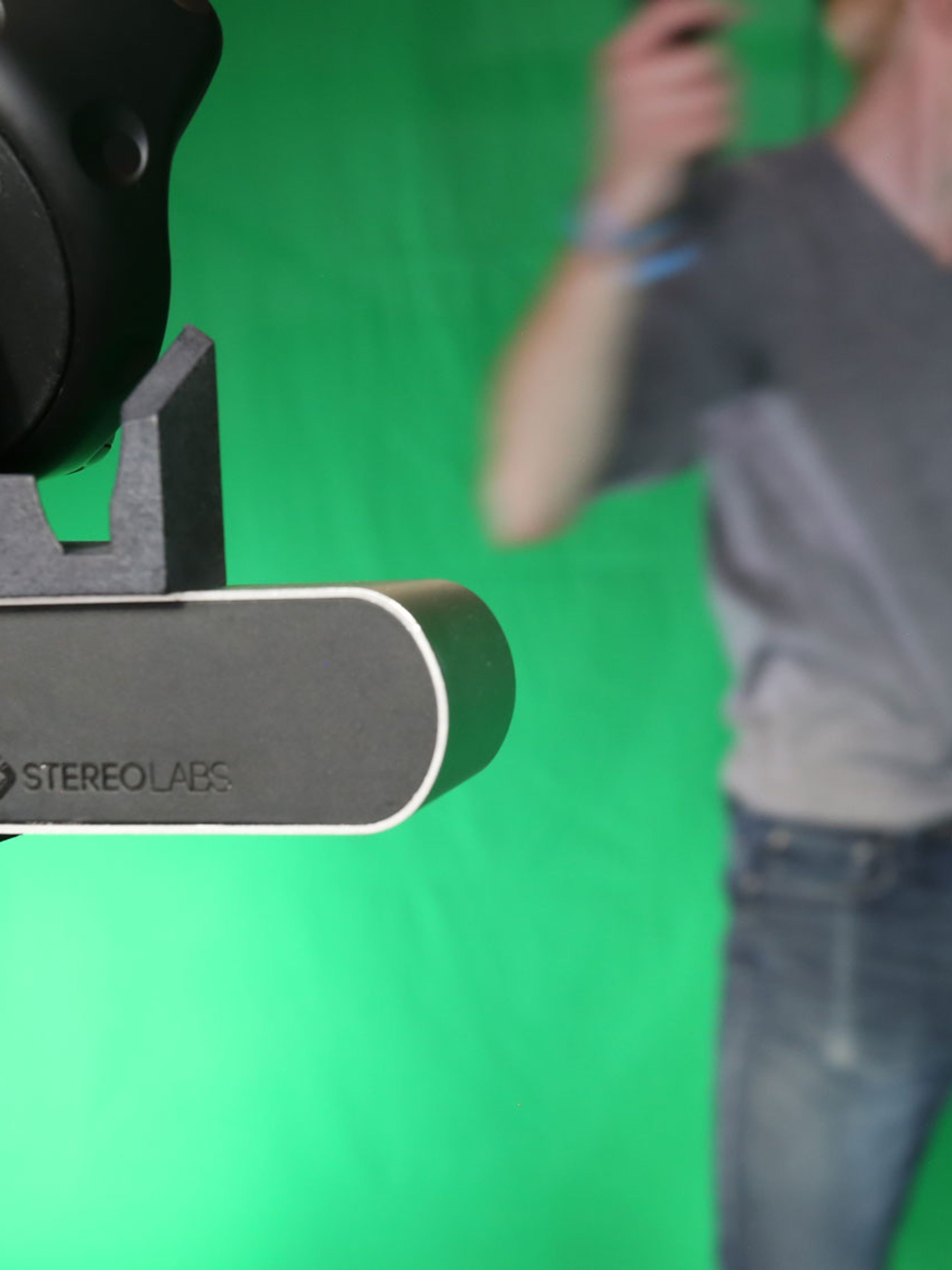
You can use an Oculus Touch Controller, a Vive Controller, or a Vive Tracker. Whichever you pick, you’ll have to physically attach it to your ZED. There are many ways to do that. If you have access to a 3D printer, you can download our mounting brace template (.step, .stl) and print it out. The same mount will fit a Vive Tracker, a Vive controller or an Oculus Touch.
If you don’t have access to a 3D printer, feel free to improvise with clamps, tape, etc. But you must ensure two things: First, that your attachment mechanism doesn’t occlude too many of the device’s sensors (hidden in Touch controllers, but indicated with divots in Vive Controllers and Trackers). Second, your attachment must be firm (no wobbling) or else you will have to recalibrate constantly.
Note: Our printable mounting brace does not fit the new ZED mini.
Note: If you’re not sure where on the ZED you should mount your controller or Tracker for the best results, know that it’s not especially significant as the calibration accounts for the offset. Mount it where you can best keep it steady. However, mounting it directly to or closer to the ZED will minimize the effect of any wobbling that does occur.
Now, you must add virtual objects that correspond to the tracked objects. Unlike the headsets, Unity does not have a native way to add in Touch or Vive controllers or other tracked objects without implementing code that interacts with its Input system. However, both Oculus and SteamVR (Vive) have free plugins you can download from Unity’s Asset Store that greatly simplifies this.
These plugins are Oculus Integration and SteamVR Plugin. If they are not already part of your project, go to the Asset Store tab within the Unity editor, search for the applicable plugin, and hit Import.

Next, you’ll see a window asking you which of the package’s assets you want to import, like when you imported the ZED package. You don’t need all of them to finish this tutorial, but unless you’re already familiar with the plugin, it is simplest just to leave them all selected and hit Import.

Unity will then import your package into your project, which may take some time. When importing either plugin, you may also get a window letting you know that Unity will automatically update some scripts of yours. If you’re working in an existing project with complex scripting already in place, you should consider making a backup of your project before proceeding. Otherwise, hit I made a backup. Go Ahead!

With the plugin in your project, it’s now time to add a virtual object to mirror its real counterpart. How you do this depends on what kind of object it is:
Oculus Touch Controller: If you don’t already have one in your scene, go to OVR ->Prefabs in the Project window, and drag an OVRCameraRig into your Inspector. Expand the new object, and expand the TrackingSpace object that’s been parented to it. The virtual object you will be using is either LeftHandAnchor or RightHandAnchor, depending on which controller you will be using.

Vive Controller or Tracker: If the tracked object you’ve mounted to your ZED is not already in the Hierarchy, then with nothing selected, right click anywhere in the Hierarchy and create a new Empty. Rename it to something indicating its role (we’ll use “ZEDTracker”). Then add the SteamVR_TrackedObject script to it by clicking Add Component in the Inspector.
In the component’s options, you’ll need to change the Index value to match the number of the device you want to use. However, this is assigned at runtime, so you will need to experiment to find which device it is. This is typically linked to the order that the objects (including the Lighthouses) were detected by SteamVR.

Tip: The [CameraRig] prefab in SteamVR -> Prefabs provides an easy way to manage your headset and first two controllers, visualize your bounds, and a few other features. It also intelligently assigns device numbers to your controllers, and tracked objects added according to Unity3D College. It’s recommended to use this prefab if it does not conflict with your project’s existing setup.
Finishing up your tracked object
Now, with either your Rift controller or Vive tracked object identified, drag your ZED prefab onto it to make it a child. That way, when the tracked object moves, Unity will know your ZED has moved by the same amount.

The last step before calibration is to disable the ZED’s own tracking system, which would otherwise conflict with the Rift’s or the Vive’s. With the ZED_GreenScreen object selected, look in the Inspecter under ZED Manager. Make sure Enable Tracking is disabled.

Note: If using a Rift, which controller is left and right will never change. But in the Vive, the ambidextrous controllers get assigned to be left or right when the game starts. If you are only using two Vive controllers total, this is important for when you parent your ZED prefab to a controller. You’ll have to position your controllers the same way when you start to make sure the correct controller is assigned.
Part 4: Calibration
Now comes the step of mixed reality where you make sure that the real and virtual cameras are precisely aligned. Traditionally, one calibrates their camera by adjusting the virtual camera until a virtual controller model overlaps a real one in the output. But the nuance of zoom, FOV and rotation can cause controllers to properly overlap in one corner of the scene but not the other, leading to calibration being one of the most loathed parts of mixed reality.
Thankfully, we’ve released a calibration tool that, with the ZED’s depth, makes calibrating your camera as simple as playing a VR game. It’s still in beta, but is available for download here.
Once downloaded, make sure your controllers/Trackers are on and tracking, start the app and hit “Play” on the first screen. The next screen will ask how you will track the camera.

- Choose None if you are not tracking the ZED or using the ZED’s own tracking.
- Choose Vive Tracker if, well, you guessed it.
- Choose Pad if you are using an Oculus Touch controller or a Vive Controller.
Hit Validate. If you chose Pad, it’ll ask you to pull the trigger of the tracked controller. Do so for the one attached to the ZED. Then you’ll be directed to put on your headset. Stand in front of the ZED, then put your headset on.
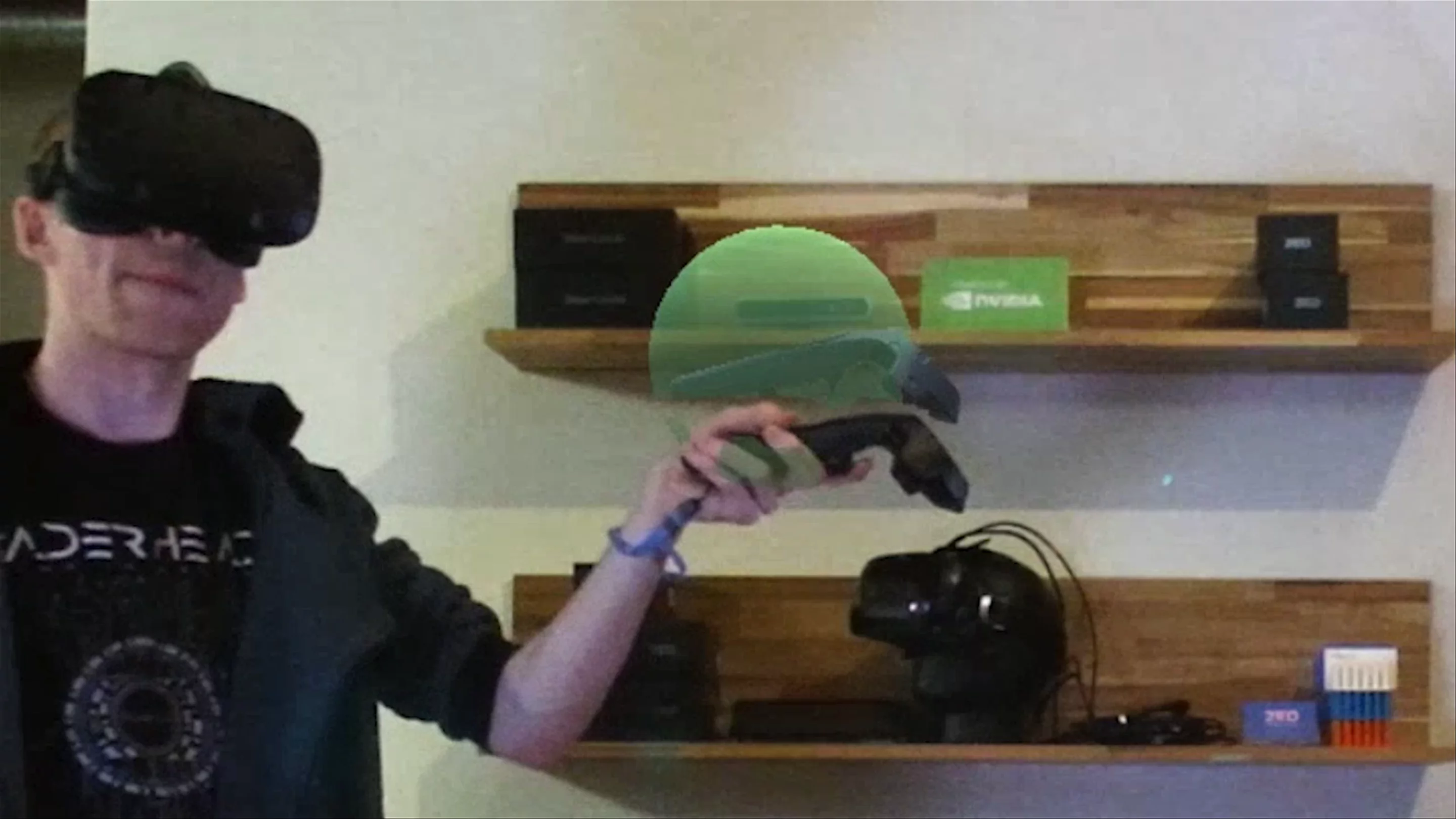
Once in VR, take a look around. You should see the following:
- A 2D screen floating in front of you showing video feed from the ZED. Look closely and you’ll see that there are virtual versions of your controllers on your screen as well. They move when you move the real ones, but are likely not lined up with their real counterparts. That’s what you’re here to fix.
- A small UI floating above one of your controllers, with a list of positions and rotations similar to the one you often see at the top of the inspector. Also, the controller this box is floating above is blue.
- A 3D “point cloud” of what the ZED sees. It may be behind you. Notice that you’re there, as well!

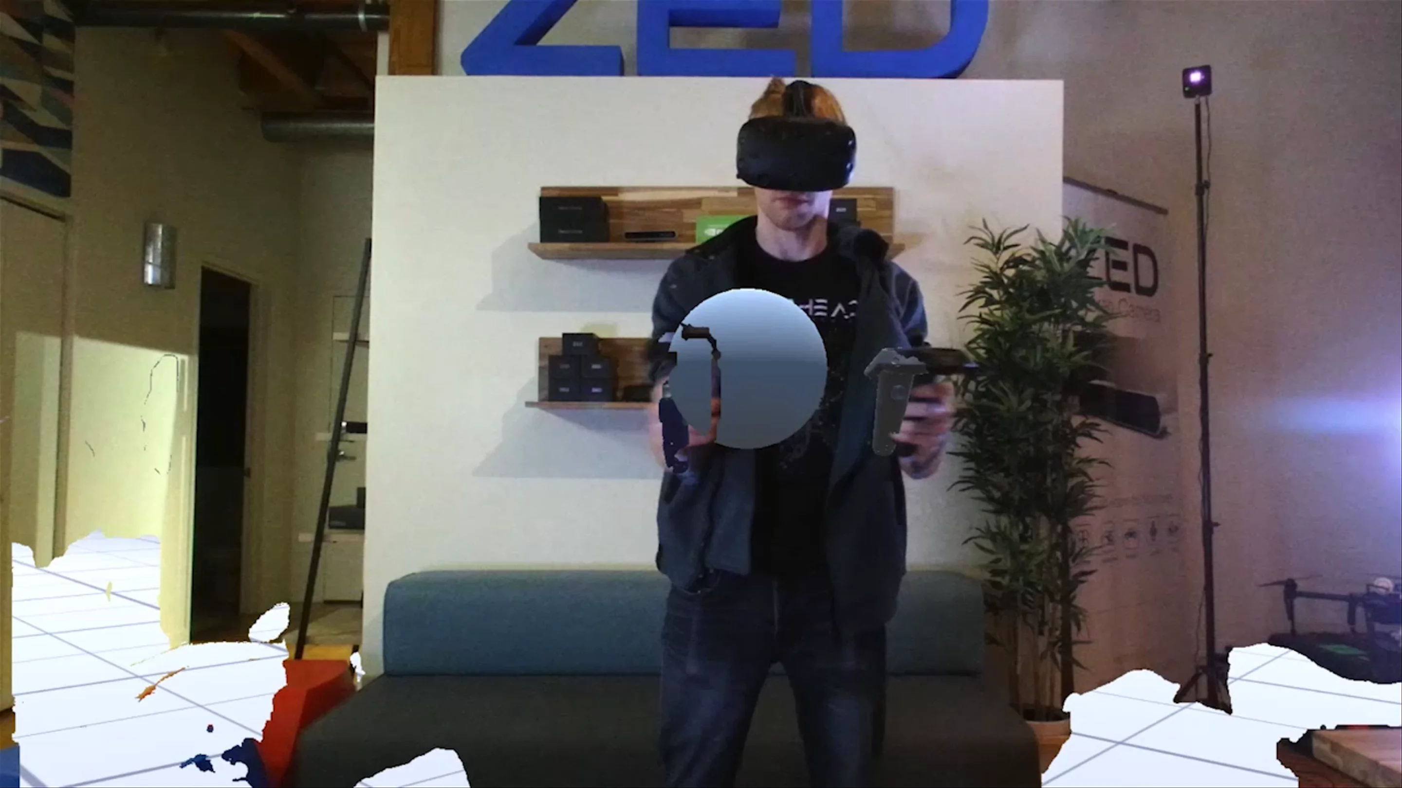
The first thing you’ll notice about the point cloud is that it’s not lined up with the real world. This may be hard to tell for most of it, but look for your own body to get a sense of how much it’s off by. The scene may be rotated oddly, positioned off-center, or both. Your first job is to roughly line this world up correctly before it gets fine-tuned by the calibration software.
To do this, look at the UI floating above your blue controller. Notice the top box is highlighted. You can tap left or right on your Touch’s joystick or Vive Controller’s touchpad to adjust these settings. Tapping up or down will scroll through them.
Adjusting the rotation may be tricky as you can’t see the real world. But if it’s correct, the 2D screen in front of you should be facing you, perpendicular to the ground. You can use this as a reference for rotation.

For position, it’s best to use your own body. It’s easiest to start with the Y value – adjust it until your clone’s head is level with yours. Then, do the Z value, so that s/he is as far away from the camera as you are. Then the X value, which you should slide until his/her hand is lined up with yours.

Once you’re satisfied, hold down the trigger on the blue controller until it goes to the next step.
Next, you will align the real and virtual controllers at several different points in space. Once you do, the tool will calculate an offset that will keep the controllers lined up wherever you go.
To do this, look for a blue sphere nearby. Put the blue controller inside the sphere, which will make the sphere turn green. Then pull the trigger.
When you do this, you’ll notice the real-world video feed on the floating screen is paused. However, the virtual controller models are not. Move both controllers so that they line up well with the real ones in your hand. Then pull the trigger.
You’ve just given the tool your first reference point. You likely noticed the environment shift a bit when you did it. You’ll have to repeat the process four more times with spheres located in different places. Each time, the video stream and the environment around you should get progressively more aligned.
Sometimes, after finishing a sphere, the environment may rotate sharply into a bad angle. This means the controller was rotated incorrectly when you pulled the trigger – it likely looked correct but was hard to verify. When this happens, simply press the grip button to remove the last reference point you added and the environment will go back to how it was before.

Tip: When you place your controller in a sphere but before you pull the trigger, move the controller so that its rotation is easy to match up with on the screen. This is not so difficult with Touch controllers, but it’s good to position the Vive controllers so that they are facing straight up or perpendicular to the camera. It can also help to hold them in such a way that your hands are occluding as little of them as possible.
Tip: If you’re watching the 2D screen, it can be easy to forget that you’re calibrating in three dimensions when you line up the controllers. Before you finalize a reference point, make sure that the controllers are at an equal distance to the camera – in other words, that they’re the same size on the screen.
Once you’ve finished the last sphere, everything should be well aligned. However, you should double-check the alignment by moving the controller to the far edges of the screen, and repeat this process at different distances from the camera.
If you find the controller loses alignment at any point, you can add another reference point to fix it. Simply pull the trigger, and it’ll freeze and let you line up the controller just like you did with the spheres. You can add as many as you want.

The alignment is quite close on the left side, but poor on the right side. He should add another reference point.
When you’re done, hit the menu button. You’ll see much of the environment turn pink. Take off your headset and you should see a screen like this:

If so, your configuration has been saved to that computer. You do not need to grab that file – the ZEDOffsetController script, which is already attached to the ZED_GreenScreen prefab, automatically loads this file at runtime.
Go back to Unity and run the scene just to test it. Hold a controller in front of the camera, and you should see that they are lined up perfectly.
Part 5: Controller Delay
With everything calibrated, the real and virtual controllers will line up. But if you move the controllers around quickly, you may notice the virtual controllers lag behind the real ones slightly.
Above: When he swings quickly, the lack of synchronization makes the lightsaber seemingly float in the air – and not in the cool Luke Skywalker way.
This is because the Constellation/Lighthouse tracking systems of the headsets are designed to update instantaneously, but the ZED has several complicated steps to process each frame, resulting in a delay that’s noticeable when the difference between frames is large (such as when the controllers are moving quickly).
Our plugin has scripts that deal with that. If you’re using Vive/SteamVR, the script has already been added to the ZED_GreenScreen prefab. It’s called ZEDSteamVRControllerManager, and you can see it in the Inspector.

If you’re using Oculus, remove that script by clicking on the gear icon in the top right and clicking “Remove Component. Then, at the bottom, click Add Component. Search for “ZEDOculusControllerManager” and click on it to add it.

Also if using Oculus, you’ll also have to add a custom precompiler directive to your project, which is easier than it sounds. Go to Edit -> Project Settings -> Player. In the Inspector, open Other Settings and under Scripting Define Symbols, add “ZED_OCULUS.” This tells Unity that it’s safe to use some code from our plugin that depends on having the Oculus plugin installed.

If your project has the controllers modeled to be something other than the default controllers, you’ll have to drag the gameobject with those controller models into the “Model To Replace” field. This is because the system works by creating clone objects that trail behind your controllers while your real controllers (which are forced to update by Oculus/SteamVR) get hidden from the ZED. If you do this, the plugin will copy the object you give it instead.

Run the scene. If you’re using Oculus, you’ll note the improvement in delay now that you’ve got the script added. Either way, slide the Latency Compensation slider around to adjust the delay, and test it until the controllers stay aligned even when you move them quickly.

Tip: If your in-game controllers are using models that replicate the real-life controllers exactly, it can be hard to catch if you add too much latency accidentally. You’ll see one controller lagging behind the other, but since you’re moving quickly, you may not be able to tell that it’s the virtual controller that’s lagging behind. Keep this in mind, or perhaps mark your real life controller with colorful tape or something similar to keep them visually distinct.
Note: These scripts use a system of clones to trail your controllers, and forces your controllers into a special layer to hide them from the ZED. This should be fine for most cases. But if your project relies on certain interactions with your controller’s gameobjects, particularly if layers are involved, you may not be able to use these scripts or will have to implement workarounds.
Once you can move the controllers very quickly and have them keep up pace, you’re ready to move on.

Swinging the controller should now look more like the image on the right. If not, continue adjusting the latency compensation.
Part 6: Background Subtraction

Now to configure the mixed reality green screen. For each pixel in the video feed, the package will ignore any of “real” pixels that are close enough to the color of your choosing. To set this up, click on Camera_Left, which is parented to the ZED_GreenScreen prefab. You’ll see a number of options under the “Green Screen Manager” script in the Inspector.
Tip: Proper lighting is essential to a quality Chroma key/green screen mixed reality setup. Lighting is a complicated art that’s outside the scope of this tutorial, but keep this in mind if you’re having trouble getting the background to subtract properly – Unity may not be where to tweak things.
Note: Because you have access to depth, there may technically be situations where a green screen isn’t needed. If the entirety of your VR environment is smaller than your real environment, with no parts of the real background that would be closer than the virtual background, then the entire background will be occluded by the real one. However, a green screen is still preferable in those situations to remove depth errors, so this option should only be explored if filming with a green screen is a big obstacle for you.

Most important are Color, Range and Smoothness. When the script goes through each frame, it’ll check each pixel’s color to see if it should turn it invisible. If you’re using a background that’s not green, adjust the Color setting to match. You can also try tweaking the shade of green to better fit the screen’s exact color and your lighting setup.
Run your scene and change each of the values below. However, as you do so, remember that stopping the scene will cause Unity to revert the settings to the way they were before you started. So either write down your final settings, or use the Save button to save them and Load them after you’ve stopped your scene.
As you change the values, you can also change the View setting to help you visualize the changes you’re making. The Alpha view is especially useful for settings that deal with which pixels are removed.


Range indicates how close a color on the spectrum can be to the exact color you chose to be invisible. You need some range because even the highest quality green screen studio has shading to it. But set it too high and parts of your subject will start to turn invisible, too.
Smoothness makes colors just outside the range get blended in. With zero smoothness, a color just outside the range is completely visible. With more smoothness, it’ll be partially visible. This is another setting to play with at runtime.
Tip: If you’re not sure where to start, set both the Range and Smoothness to zero. Then raise the Range until it’s as good as you can make it look, then raise the Smoothness until it’s near perfect.
The rest of the settings are less critical, but help you solve specific issues:
Erosion: This setting removes the edges of real objects in the video stream where they border with the green area. This is useful because those edges will sometimes be blended together, resulting in your subjects having thin green outlines. Play with this setting if that’s the case.

Before erosion

After erosion
White Clip/Black Clip: Alpha values (transparency) above the White Clip value will be set to 1 (fully opaque), and alpha values below the Black Clip value will be set to 0 (fully transparent). In other words, White Clip makes nearly opaque pixels fully opaque, and Black Clip does the same for nearly invisible pixels. This helps you remove noise that results from your smoothness setting.

Before white clip

After white clip
Despill: This makes the non-green pixels look even less green (or whichever color you’re using). This is useful because you often have slight green reflections on a subject, even on clothes and other non-reflective materials, thanks to the bright lights and the big green walls. However, raising this setting makes things look less vibrant, so don’t raise it any more than you need.

Before despill

After despill
Garbage Matte: The Garbage matte lets you extend the virtual world beyond the green screen’s limited size. In short, it lets you paint a box where you’ll see your subject, and everything outside that box will be automatically deleted as if it were a green screen. This is useful if your green screen is too small to fill everything the ZED can see.
When you enable the Garbage Matte setting, you’ll see a few more buttons appear.

While the game is running, press Place Markers, and click on the four corners of your Game window (not your Scene window) where you want this “box” to appear. Each time you click, you should see a ball appear there. (If not, it may be behind a real object.) Once you have four of them, it should create a white plane that represents the box.

Click Apply and it’ll start working. To preserve this matte for later, you’ll have to hit Save to save all your settings, and load them after you stop the scene.
Part 7: Virtual Lighting
Now we’re going to make it so that the virtual lights in your game affect your real-world subjects, as well. That means bright flashes, colors and shadows on your real-world player from lights that don’t actually exist. This adds another layer of realism to the scene, as seen above, and will put your final product a cut above most mixed reality productions.

The left scene has virtual lighting applied to the real world. The right scene does not.
Doing this is straightforward – we’ll simply add a script to each light we want to affect the real world, and the Plugin will handle the rest. But there are some limitations you must keep in mind:
- You can have a maximum of 8 lights set to work on the real world at the same time
- Only Directional lights can cast shadows – we recommend exactly one per scene to get the desired effect
- This only works on Point, Spot and Directional lights. Area lights, emissive materials and lights instantiated by a particle system aren’t supported.
Note: The specifics of lighting a Unity scene is outside the scope of this tutorial, but Unity provides detailed documentation on this topic here. If you are working with a new scene, we suggest experimenting with a Point light, and having at least one Directional light in the scene for shadows.
Select each light you want to shine on the real world in the Hierarchy. Then, in the Inspector, hit Add Component. Then type “ZEDLight” and click on the script when it appears in the list.

After you’ve done this with all the lights you want, test the scene and see how they look on your subject. You can move the light around in the Scene window at runtime to check its effect at different distances. You can also modify the parameters of the light in the Inspector, such as Color, Intensity and Range.
Matching Virtual and Real Lights
Depending on your real-world subject and lighting, you may find that a light’s effect on virtual objects and real objects differs significantly – such as a torch’s flame brightly illuminating the virtual ground but only slightly illuminating the person holding it.
To fix that, we’ll stop that light from casting on real objects, and instead create a duplicate light that only casts onto real objects, so that we can tweak it without affecting the real world.
First, select the light in question. In the inspector, click on the tiny gear icon at the top right of the ZED Light script. Then click “Remove Component.”

Then, right click on the light in the Hierarchy and click “Duplicate.” You’ll see a copy of that light appear underneath it. To make sure the light’s stay together, click and drag the new light onto the old one to make it a child of it. That way, if the original light moves, the new one will move as well.
With the new light selected, rename the new light to something that indicates its specific role, like “Point Light – ZED Clone,” and add the ZEDLight script to it as you did before. Then go to the light’s Culling Mask value and click “Nothing.” This will tell it not to affect real objects.
Now run the scene, and with the new light selected, tweak its settings in the Inspector. Most likely, you’ll be tweaking Range and Intensity. Once the lighting on the real and virtual objects are similar enough, write down the values you changed and stop the scene. Re-add those values, and you’re finished.
Part 8: Final Output

Your scene should now be looking good. It’s time to get it ready for recording or streaming. We won’t do this in the Unity editor, as you want something full screen, and to drop the editor’s burden on performance. We’re going to build your project into a standalone application.
Building your Project
Go to File -> Build Settings to open up a new menu. If you haven’t yet done this for your current project, you’ll have to add the scene to the Scenes In Build section by clicking “Add Open Scenes.”

Hit Build and Run. You’ll get a prompt asking where you want to save your game. You’ll be able to run this application in the future without the editor, so remember where you put it. Hit Save, and wait for it to build your game. Once it’s done, it will open a new window. You should see your scene inside like before, and your ZED will start automatically.

Configuring OBS
Now, open OBS, which you can download and install here if you haven’t done so already. OBS is free software for capturing video inputs, processing them in real-time, and recording or streaming them. (If you prefer to use another program for capture, you may do so and skip the rest of this section.)

Click the plus sign under Sources. Click “Game Capture.”

Note: Choosing “Window Capture” can provide similar results, and the configuration process is basically identical. It’s less performant and won’t work if you want to make your game full-screen, but it’s more stable than Game Capture.
Name this new Source whatever you want and hit OK.

In the next screen, change the Mode to “Capture Specific Window.” This will create some new options. Change the Window setting to the name of your application. Disable Capture Cursor and press OK.

To capture your game’s audio, add another source and choose “Audio Output Capture.” Again, name it what you’d like. You’ll get another window like the one where you configured your Game Source, but with only one relevant option: Device. Choose the output device, like your speakers or VR headset headphones. Leaving it as “Default” may also work. Then hit OK.

Note: Your scene may have started with an audio output capture source when you created it. If so, double-click that one to check the settings instead.
If you want to record your voice, which is likely if you’re streaming, add an “Audio Input Capture” and choose the relevant microphone (usually your headset).
Back at the main window, you’ll see your game window displayed in the main screen with a red outline. If your window resolution matches the OBS canvas resolution, your game window should neatly fit the output window in OBS. If it doesn’t, you can click and drag the corners of the red box to scale it, and drag anywhere on the image to move it around.

Note: If you want to configure OBS’s output resolution, which we’ll summarize later, it’s a good idea to do that before you position the frame as it may change.
Another way to adjust the positioning and scale is to right-click anywhere on the scene and hover over Transform. You’ll have a number of options, like “Fit to Screen,” which can quickly fit it. You can fine-tune the settings by clicking on “Edit Transform,” which lets you move or scale the images pixel by pixel.

With your scene set up, you’re just about ready to go! The last step is to configure your Video and Output settings to match what you want. To get to the settings, find the Settings button on the lower right. It’ll open up this window:

As the proper configuration varies wildly depending on your intended final product, your target platform, your system and other factors, we’ll just skim over these.
- General: Preferences for OBS itself. Not related to the output.
- Stream: Some settings you’ll have to provide before the “Start Streaming” button on the main window will do anything. Setting it up is different depending on your platform, so you should seek out a different tutorial specific for that platform – many make use of OBS.
- Output: Quality and formatting settings for both streaming and recording, along with some miscellaneous settings. This is also where you set the path that recorded files are saved in. If you’re recording, note that the default recording format is .flv, which is less portable than other file formats like .mp4, so consider changing it before recording.
- Audio: Quality settings for your sound, along with optional hotkey settings if you want to quickly enable/disable an input device mid-stream (push-to-talk).
- Video: The resolution of the output. Note that the settings are separate for the Canvas (the preview window) and the actual output. Ideally, you should make these resolutions the same. But if you can’t, at least make sure they’re the same aspect ratio or else your output will get cropped and/or distorted.
- Hotkeys: Exactly what you’d expect.
- Advanced: Non-critical but useful functions (such as adding a delay to your stream) and settings for experts (like color formats).
And you’re done! Go back to the main window and hit “Start Streaming” or “Start Recording” to create awesome mixed reality content for the world.
We’d love to see what you create! Tell our MR developer evangelist Chris about any cool content you make, we’ll even help share it.