ZED Box Mini Connectivity
Connection Ports
Front side
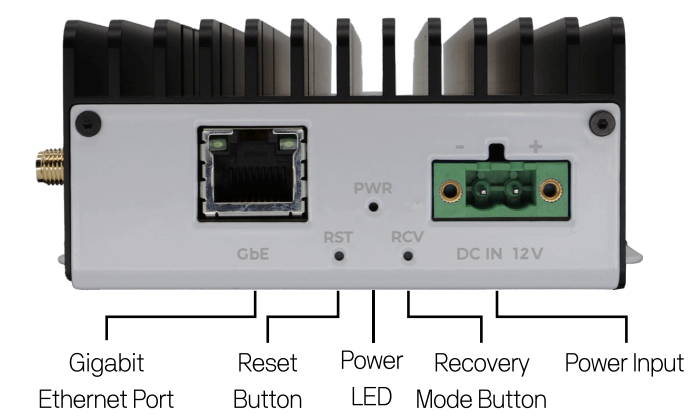
- Power connector
- Ethernet connector
- Power LED indicator
- Reset button
- Force Recovery button
Left side
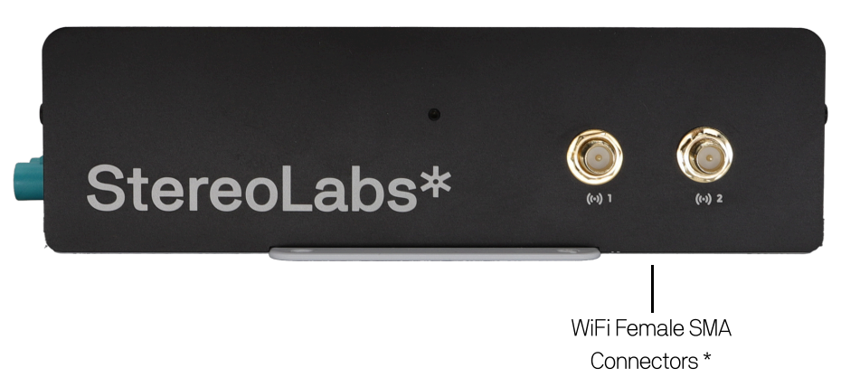
- [optional] Wi-Fi antenna connectors
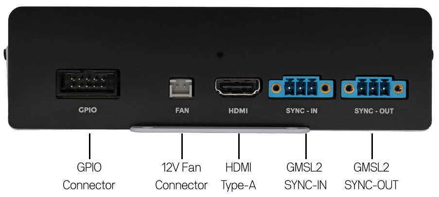
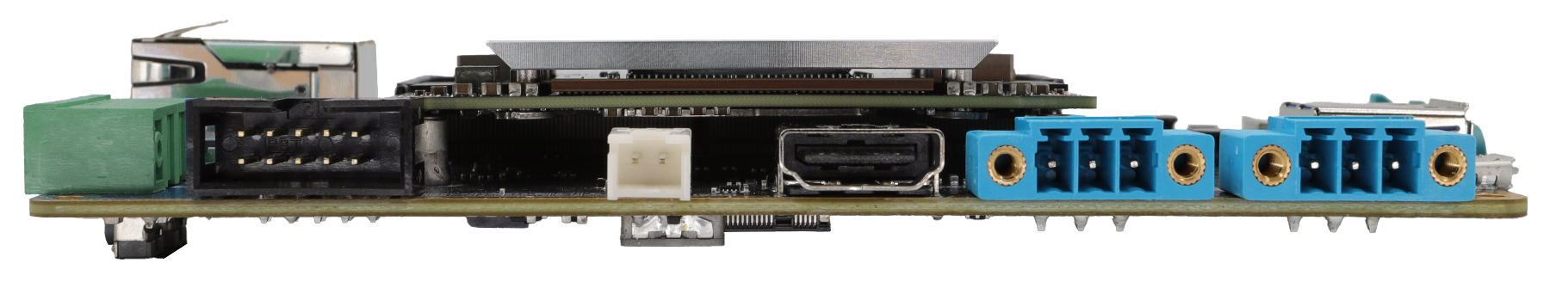
Rear side
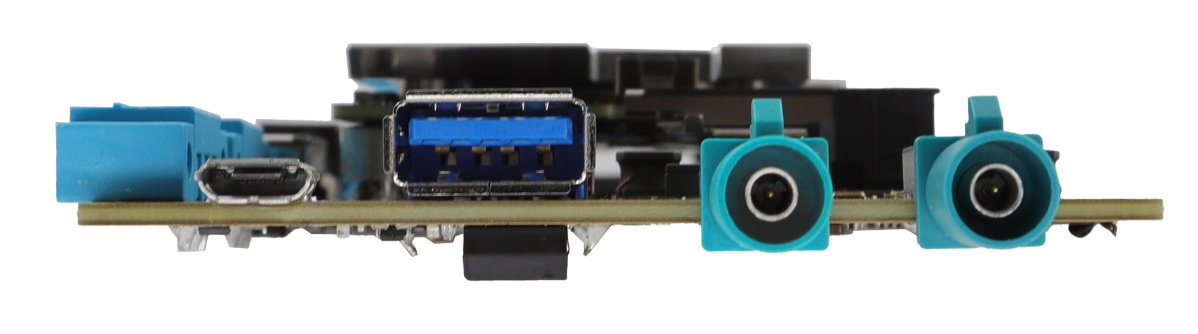
Right side
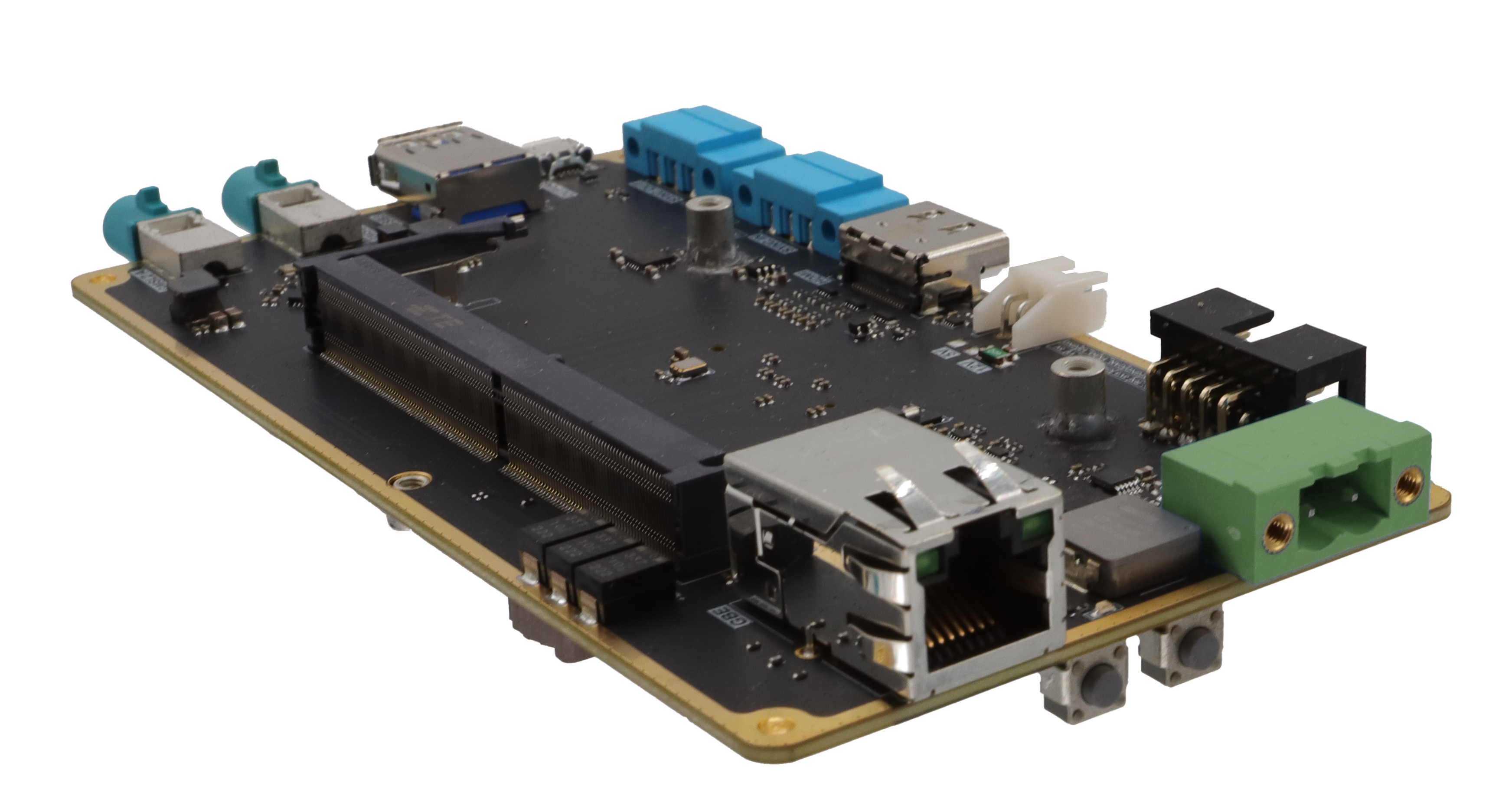
Carrier Board
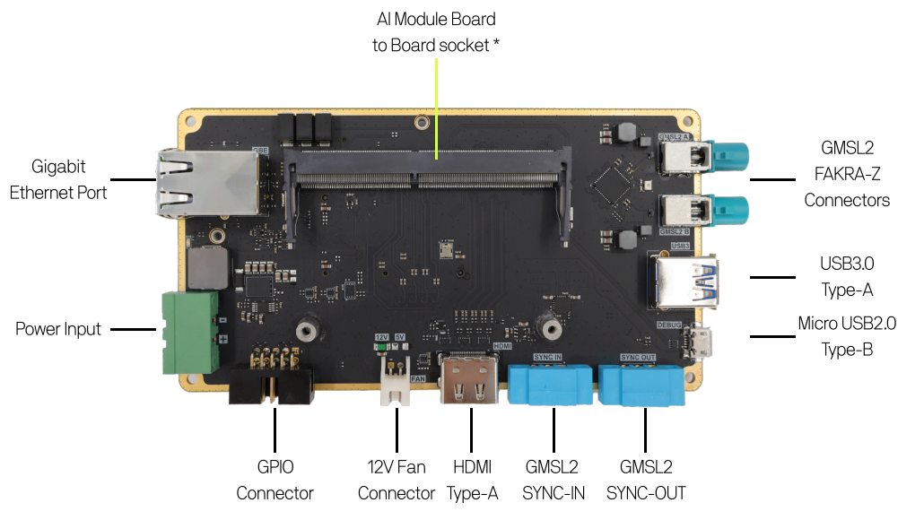
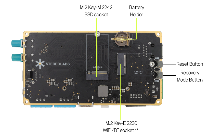
* [Optional] Orin NX and Orin Nano compute modules.
** [Optional] Intel AX210 Module or compatible.
Use a CR1220 coin cell battery to enable the system RTC.
Power input
DC 10.5V to 13.5V - 60W max
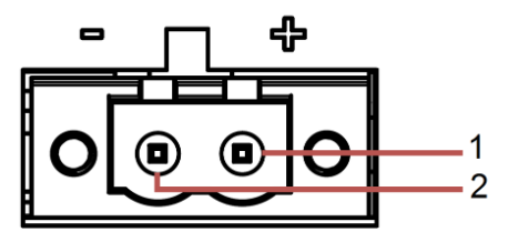
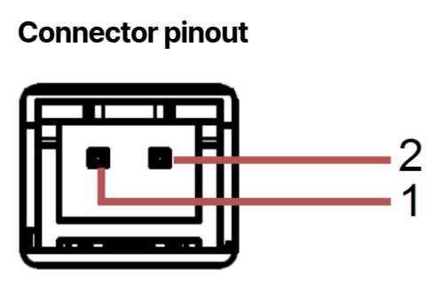
Pinout Power
- #1 - DC IN 12V
- #2 - GND
Use the provided 12V 60W power supply or a regulated 12V input.
Please ensure that the voltage of DC IN 12V is correct before connecting it to the system.
Supplying a voltage over 16V could damage the system.
Connector type: TBP01P1W-508-02GR
For battery power, we recommend using a 4S Lithium or Lithium Polymer battery with a 60W 12V DC-DC converter to guarantee a stable power voltage.
Ethernet (LAN)
The ZED Box Mini series comes with one Gigabit Ethernet LAN port supporting 10/100/1000 BASE-T with an RJ45 connector. This connector is equipped with two green LEDs indicating LAN link and activity on this port.
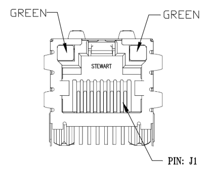
Pinout LAN
- #1 - MDI0_P [TX+]
- #2 - MDI0_N [TX-]
- #3 - MDI1_P [RX+]
- #4 - MDI2_P
- #5 - MDI2_N
- #6 - MDI1_N [RX-]
- #7 - MDI3_P
- #8 - MDI3_N
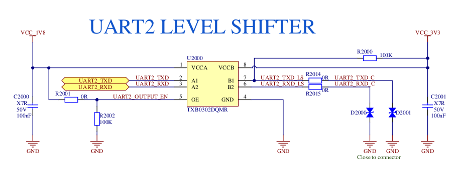
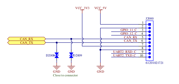
GPIO
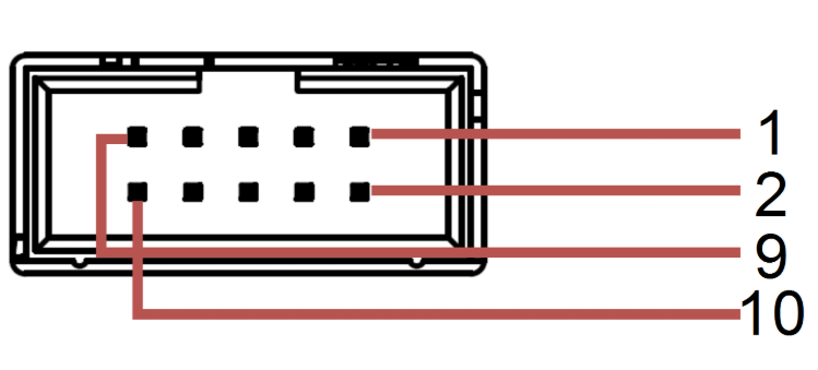
Pinout GPIO
- #01 - VCC_5V
- #02 - GND
- #03 - GPIO_11 [CMOS-3.3V]
- #04 - GPIO_12 [CMOS-3.3V]
- #05 - CAN_RX [CMOS-3.3V]
- #06 - CAN_TX [CMOS-3.3V]
- #07 - VCC_3V3
- #08 - GND
- #09 - UART_RXD [CMOS-3.3V]
- #10 - UART_TXD [CMOS-3.3V]
- The UART pins on this connector are 3.3V compliant.
- The GPIO pins on this connector are 3.3V compliant.
- The CAN pins on this connector are directly connected to the Jetson™ module and are CMOS-3.3V compliant. Please ensure to use a dedicated CAN transceiver on this end of the system before using this connection as a CAN BUS. NVIDIA® recommends using the Waveshare SN65HVD230, featuring the TI SN65HVD230 CAN transceiver.
Using electrical signals that do not conform to the specifications may cause significant damage to the device, which is not covered by the warranty.
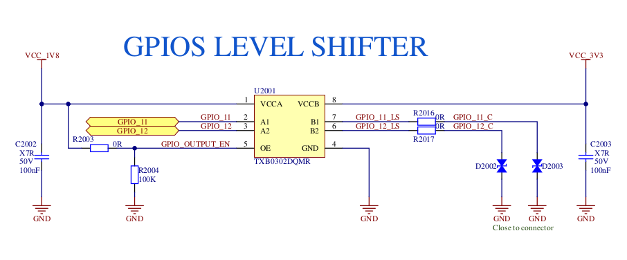
Using GPIO_11 and GPIO_12
Please refer to the dedicated documentation page: Using the GPIOs on your ZED Box Mini.
FAN
The ZED Box Mini includes a dedicated 12V-compatible fan connector to support active cooling solutions.
The fan with a mounting plate is also available for purchase on our website, recommended for high-power workloads on the selected NVIDIA® Jetson™ module.
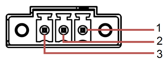
Pinout FAN
- #01 - FAN_12V
- #02 - GND
If using a third-party fan, ensure it operates at 12V and does not exceed 500mA of current draw. Exceeding this limit will trigger the PTC (Positive Temperature Coefficient) fuse on the carrier board, interrupting power delivery and preventing fan operation.
The connector is a JST 2-pin connector (2.50 mm pitch) that mates with XHP-2.
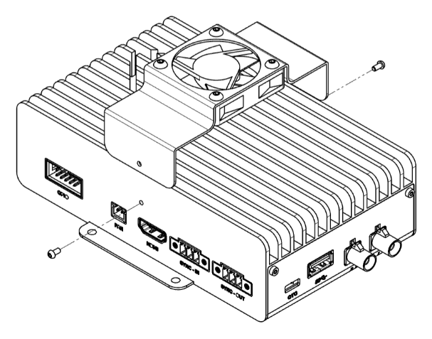
Installing the FAN on the aluminum case
-
Screw the fan onto the aluminum support using the screws and inserts.
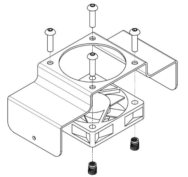
-
Place the support on the ZED Box Mini and fix it on the sides using the two screws.
-
Connect the fan connector to the fan port.
HDMI
The ZED Box Mini features an HDMI 1.4 to 2.1 type-A compliant connector, depending on the chosen Jetson™ for the system, to display video with a maximum resolution of 3840×2160 @60Hz.
For additional information regarding the pinout, please refer to the HDMI standard.
SYNC-IN
The synchronization-input connector is used as a frame-sync trigger input to synchronize image acquisition on multiple GMSL2 cameras connected to different ZED Box Minis.
The connector is a Same Sky (formerly CUI Devices) 3-pin Terminal Block connector that mates with TBP02P1W-381-03BE.
Pinout SYNC-IN
- #01 - TRIG_INFO
- #02 - GND
- #03 - TRIG_IN
Set the device in slave mode
You can configure the ZED Box Mini in slave mode to synchronize GMSL2 camera image acquisition with an external trigger signal. This enables seamless integration with other ZED Box Minis or third-party sensors through the SYNC-IN connector.
To enable the external trigger input, follow these steps:
-
Set
sync_mode=2in the file/etc/systemd/system/zed_x_daemon.serviceto enable the external trigger input. -
Reload the systemd configuration:
-
Connect PIN #02 (
GND) to the ground signal of the trigger source. -
Connect PIN #03 (
TRIG_IN) to the trigger signal source, i.e., a 3.3V square wave signal. -
Restart the driver by restarting the ZED X daemon service:
To verify that the Slave configuration is active, run the command:
The output should be similar to:
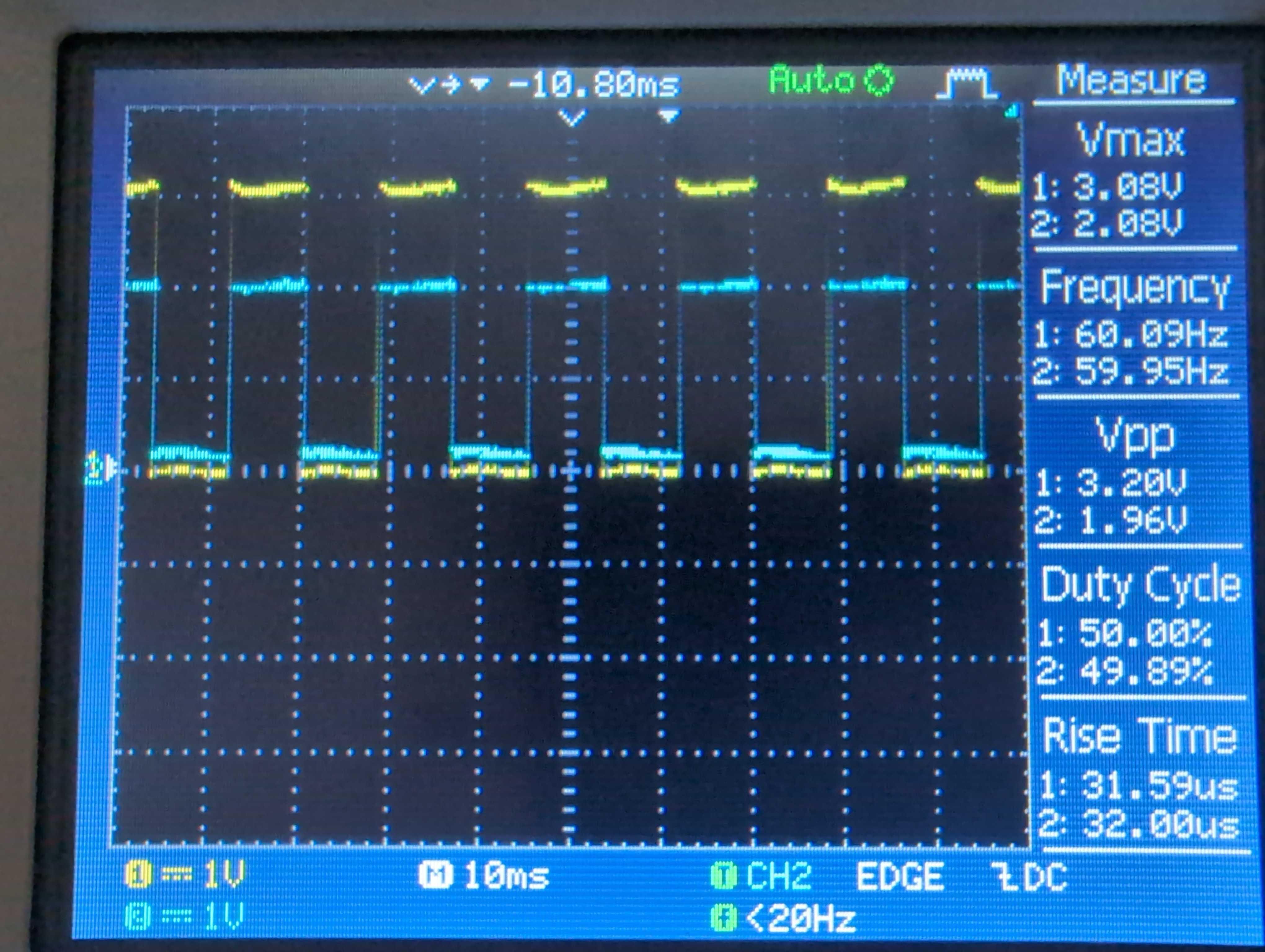
You must use an external trigger signal with the following characteristics:
- Square wave
- Amplitude: 3.3V +/- 10%
- Frequency: Match the camera grab frame rate setting used with the ZED SDK - 15Hz, 30Hz, 60Hz, or 120Hz
SYNC-OUT
The synchronization-output connector is used as a frame-sync trigger output to synchronize image acquisition on multiple GMSL2 cameras connected to different ZED Box Minis.
The connector is a Same Sky (formerly CUI Devices) 3-pin Terminal Block connector that mates with TBP02P1W-381-03BE.
Pinout SYNC-OUT
- #01 - GND
- #02 - GND
- #03 - TRIG_OUT
Set the device in master mode
You can configure the ZED Box Mini in master mode to generate an external trigger signal for synchronizing multiple devices. This enables seamless integration with other ZED Box Minis or third-party sensors through the SYNC-OUT connector.
The ZED Box Mini is configured to operate in master mode by default.
In any case, if you change the mode, you can set the device back to master mode by following these steps:
-
Set
sync_mode=0in the file/etc/systemd/system/zed_x_daemon.serviceto enable the external trigger output. -
Reload the systemd configuration:
-
Connect PIN #02 (
GND) to the ground signal of the trigger source. -
Connect the external device to PIN #03 (
TRIG_OUT) to receive the trigger signal. -
Restart the driver by restarting the ZED X daemon service:
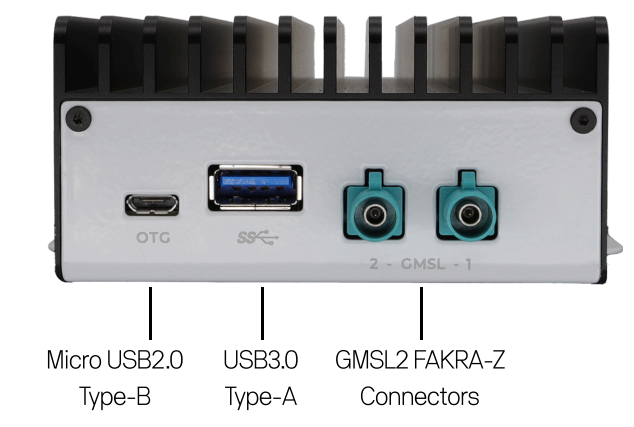
GMSL2
The ZED Box Mini and the Mini Carrier board offer two separate FAKRA connectors for GMSL2. Each GMSL2 camera is connected to the box through a single coaxial cable, available in different lengths on our store. Using GMSL2 (Gigabit Multimedia Serial Link) connections, the cameras connect to a two-port deserializer, the MAX9296A, which converts the video stream to MIPI CSI-2 and transmits it to the chosen Jetson™.
Supported GMSL2 camera combinations
It is possible to connect only one camera to each single GMSL2 port.
The table below illustrates the different behaviors that can be expected according to the camera type:
It’s not possible to connect two ZED X One 4k cameras. Only one ZED X One 4k connected to port #0 is supported.
USB 3.0
A USB 3.0 Type-A connector supports up to 5Gbps data rate. It is compliant with the requirements of Super Speed (SS), High Speed (HS), Full Speed (FS), and Low Speed (LS).
For additional information regarding the pinout, please refer to the USB Type-A standard.
Micro-USB 2.0 - OTG
The ZED Box Mini features a Micro USB 2.0 Type-B that can be used for OTG functions or paired with the Recovery button to flash a new image on the device. In non-recovery mode, this OTG port provides a serial output that can be used to monitor and access the device through a serial console.
For additional information regarding the pinout, please refer to the Micro USB 2.0 Type-B standard.
Multi-device synchronization
The ZED Box Mini enables precise camera synchronization across multiple units via GMSL interfaces, ensuring accurate data alignment for large-scale deployments. This capability is essential for intelligent systems requiring synchronized multi-camera vision, such as smart infrastructure, entertainment venues, and logistics applications.
Three-Device Synchronization Example
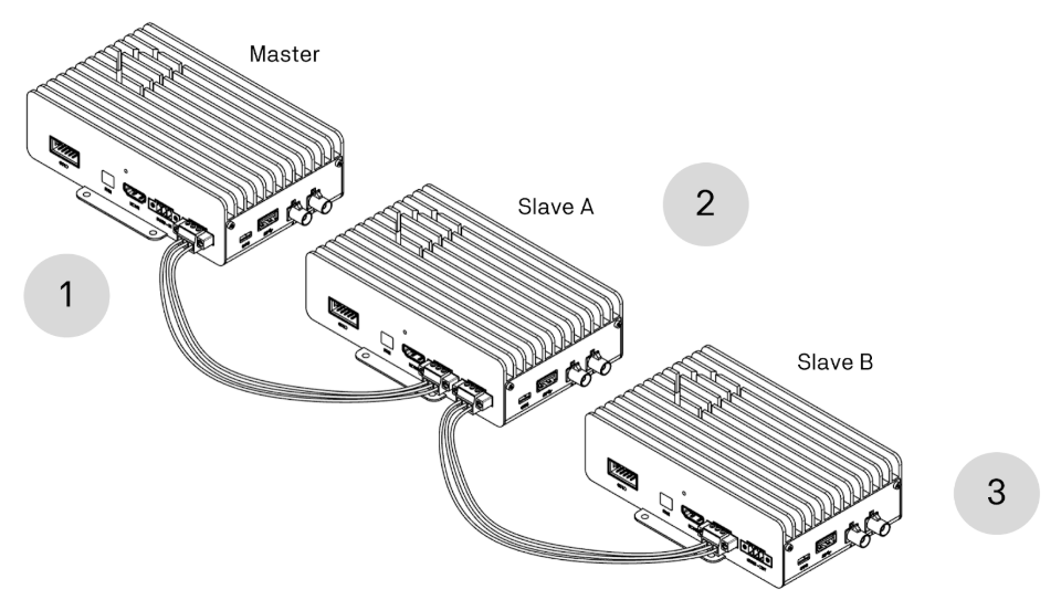
- The Master device generates and transmits a clock signal to trigger frame acquisition for its connected GMSL2 cameras.
- Slave A receives the Master clock signal and triggers frame acquisition for its connected GMSL2 cameras, then forwards the signal to Slave B.
- Slave B receives the Master clock signal through Slave A and triggers frame acquisition for its connected GMSL2 cameras.
Additional ZED Box Mini units can be daisy-chained in the same manner, propagating the Master clock signal across multiple devices in real time.
Multi-device synchronization is only available for GMSL2 cameras. USB 3 cameras do not support this feature.
Configure the devices
To enable multi-device synchronization, designate one ZED Box Mini as the Master and configure all others as Slave units.
Once properly configured, all grab function calls made through the ZED SDK on each device will be synchronized to the Master clock signal with an accuracy of approximately 15 µs.
Configure the Master device
-
Open a terminal on the ZED Box Mini designated as Master.
-
Enable external trigger output by setting
sync_mode=0:
Configure the Slave devices
-
Open a terminal on each ZED Box Mini designated as Slave.
-
Enable external trigger input by setting
sync_mode=2: -
Verify the Slave configuration on each device:
Expected output: