Setting up the ZED X One Stereo
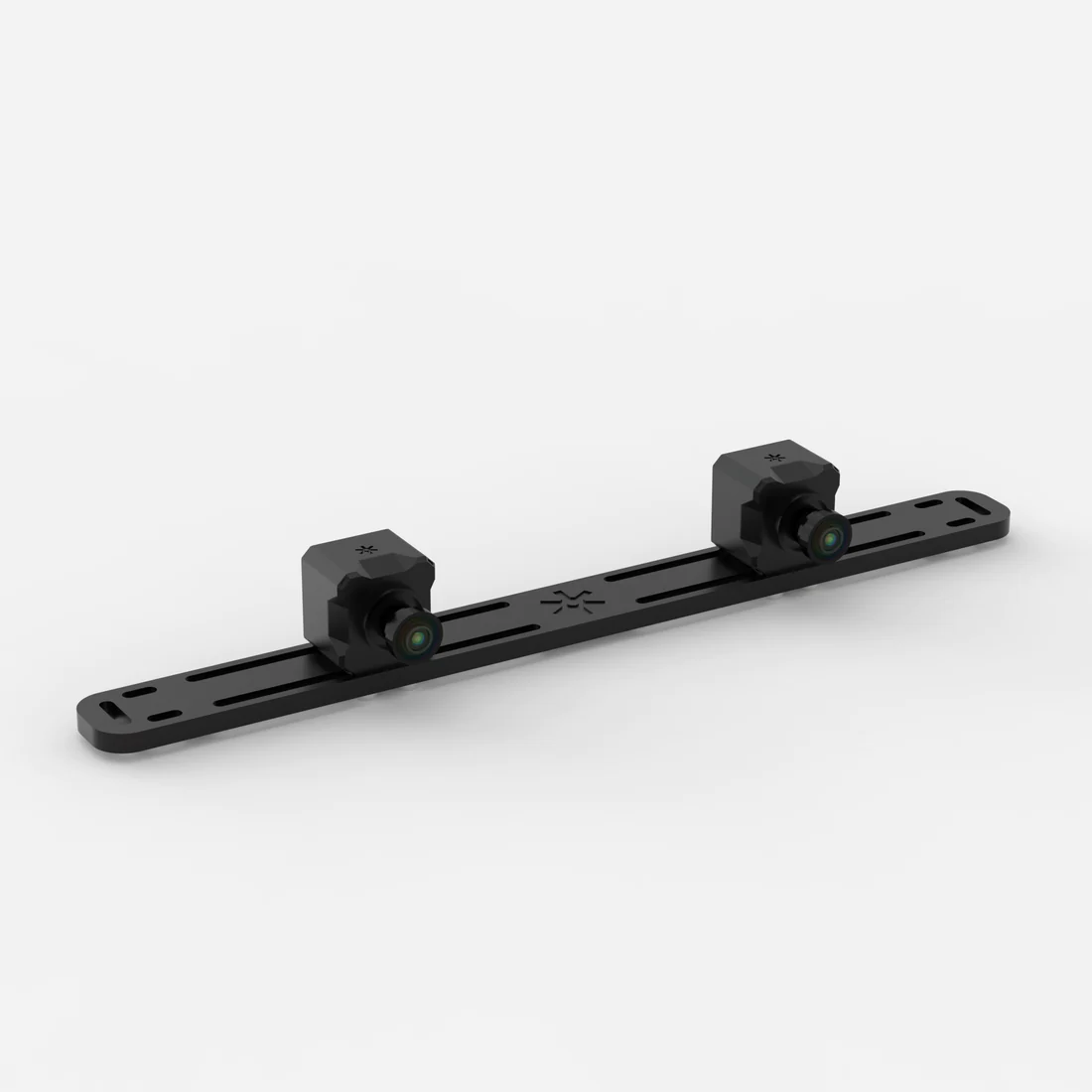
Two ZED X One cameras can be combined to create a Virtual Stereo Vision system, functioning as a single stereoscopic camera similar to the ZED 2i or ZED X.
When creating a stereo rig, it’s essential that the two cameras provide synchronized image capture to ensure accurate depth perception. The ZED X One cameras, when used with ZED Link capture cards, ZED Box Orin, or ZED Box Mini, support hardware synchronization via the GMSL2 interface. This synchronization ensures that both cameras capture images simultaneously, with an accuracy of 15 µs.
This configuration enables you to build a custom stereo rig with a baseline (distance between cameras) tailored to your specific application requirements:
- Short baselines (down to 25 mm with ZED X One S models) are ideal for close-range depth perception.
- Long baselines (up to several meters) provide enhanced accuracy for long-range applications.
The following diagram illustrates the Field of View (FOV) overlap when two ZED X One cameras are positioned side by side with a baseline “B”.
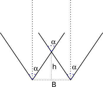
For a fixed minimum depth value h, you can calculate the required baseline B as:
Conversely, if you fix the baseline B, the corresponding minimum depth value h is:
Where α is the horizontal Field of View (FOV) of the camera model used.
You can retrieve the Field of View (FOV - α) for each camera model from the respective product datasheet.
To obtain a minimum depth value that allows for a usable depth map, it is required to apply a “6x” factor to h. This is required to guarantee that the field of view of the two cameras has a good overlapping area:
The maximum depth (in meters) can be calculated with the formula:
Where:
- B is the baseline in meters
- F is the focal length of the optics in meters (you can find this information in the product datasheet)
- sens_w is the size of the CMOS sensor in meters (you can find this information in the product datasheet)
- res_W is the image resolution (you can use 1280 as a good approximation)
For detailed guidance on assembling your stereo rig, refer to the support article on setting up your stereo rig with two ZED X One cameras.
Install the Software
You need two main software components to operate a dual ZED X One stereo system:
- The GMSL2 driver to configure the system to control the GMSL2 cameras and retrieve images and inertial data.
- The ZED SDK to process the stereoscopic data.
Install the GMSL2 driver
Important: This procedure is valid only for ZED Box Orin, ZED Box Mini, or official NVIDIA® Jetson™ development kit platforms equipped with a ZED Link GMSL2 Capture Card. If you are using a different GMSL2 system, please refer to the specific installation instructions provided by your hardware manufacturer.
The ZED X One cameras require a GMSL2 driver to operate correctly. This driver configures the GMSL2 device and is hardware-dependent.
Download the appropriate driver from the ZED X Driver download page.
Always verify the latest driver version available on the download page. We recommend installing the most recent version.
Select the driver matching your hardware configuration and install it:
Where:
X.X.Xis the driver version<board>is the board model<deserializer>is the deserializer typeL4TZZ.Z.Zis the Jetson™ Linux version (corresponding to your JetPack version)
Example: For ZED X Driver v1.3.2 on L4T 36.4.0 (JetPack 6.2) with the StereoLabs ZED Link Duo GMSL2 Capture Card:
If the installation fails due to missing dependencies, install libqt5core5a:
After installation, reboot your NVIDIA® Jetson™ platform.
For troubleshooting, refer to the ZED Link troubleshooting guide.
Install the ZED SDK
The ZED SDK enables processing of stereoscopic data from dual ZED X One cameras configured as a virtual stereo system. The sl::Camera class (C++ | Python | C# | C) provides the core functionality for depth computation and 3D perception.
To get started, download and install the ZED SDK on your NVIDIA® Jetson™ platform.
Configure the Custom Stereo rig
The two ZED X One cameras should be rigidly mounted parallel to each other at a fixed distance (baseline). It is critical that the cameras don’t move in rotation or translation relative to each other over time. Any small movement will require a new calibration. The mechanical stability should be adapted to the usage conditions, especially vibrations or shocks that could affect the cameras’ alignment and significantly decrease the accuracy of the depth processing.
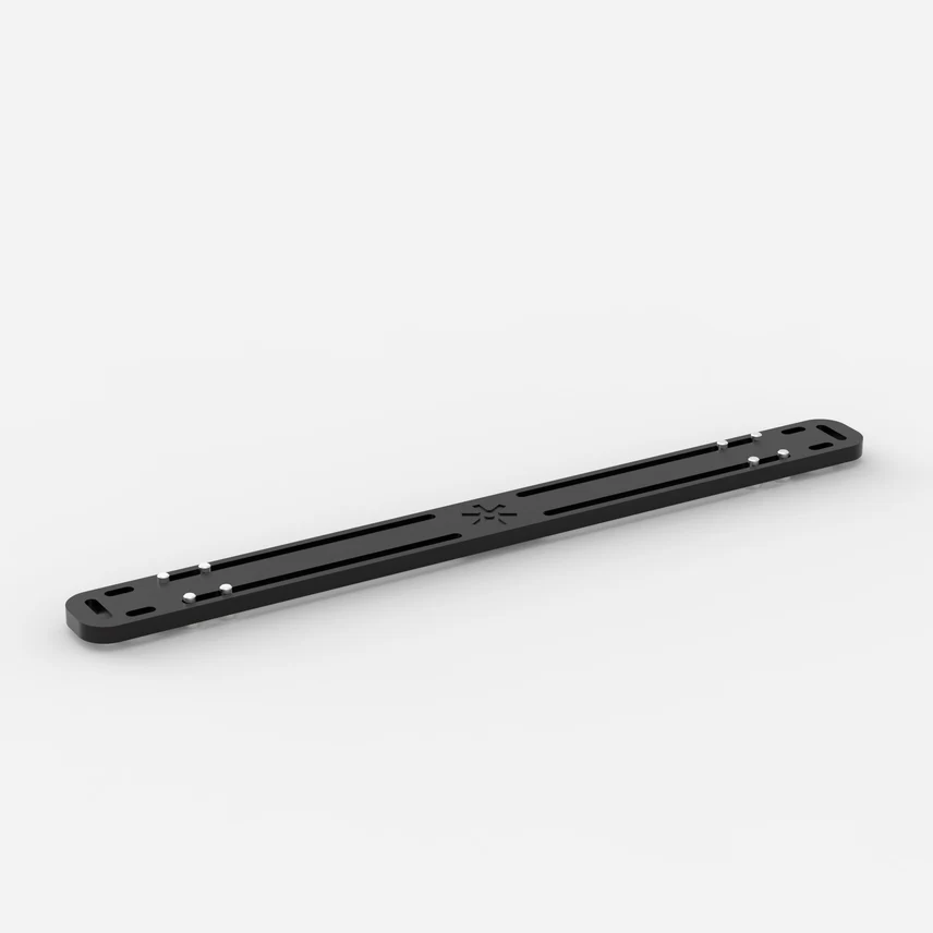
In the StereoLabs store you can find a Dual Camera Mount for ZED X One to mount two ZED X One cameras at a fixed distance and test the stereo setup.
Calibrate the Custom Stereo rig
The calibration step is mandatory to perform depth estimation using the ZED SDK API.
This procedure determines:
- Intrinsic parameters: The optical characteristics of each monocular camera (focal length, optical center, distortion).
- Extrinsic parameters: The relative position and orientation between the two cameras in the stereo rig.
Calibration must be performed in the following scenarios:
- Initial setup: When first assembling your dual ZED X One stereo rig.
- Mechanical changes: If the relative position or orientation between the cameras is altered or modified, even if slightly.
- Physical impact: After any shock, vibration, or mechanical stress that could affect camera optical axis alignment.
If the mechanical configuration changes and the system is not recalibrated, depth measurements will be compromised and inaccurate.
Understanding Calibration Parameters
While the monocular ZED X One cameras come with pre-assembled optics that are factory-calibrated for intrinsic parameters, the calibration process for a custom stereo system typically refines the intrinsic parameters and estimates the custom extrinsic parameters to achieve optimal depth estimation accuracy.
Only the extrinsic parameters (translations and rotations between cameras) are affected by mechanical changes to the rig. However, refining intrinsic parameters during calibration can improve overall accuracy.
User Responsibility
It is the user’s responsibility to:
- Perform the calibration procedure when required
- Manage and distribute the calibration files to all systems using the custom stereo rig
- Recalibrate when mechanical changes occur
Use the ZED OpenCV Stereo Calibration Tool
We provide a calibration tool using the OpenCV library to perform the stereo calibration of the dual ZED X One system. It’s not mandatory to use this tool, but it simplifies the calibration process and generates calibration files compatible with the ZED SDK.
The tool is open-source and available on GitHub.
Build the tool
Open a terminal on your Linux system and execute the following commands:
Perform the Stereo Calibration
The Stereo Calibration Tool enables precise calibration of ZED stereo cameras and custom stereo rigs (e.g., two ZED X One cameras) using a checkerboard pattern. This process computes intrinsic camera parameters (focal length, principal point, distortion coefficients) and extrinsic parameters (relative position and orientation between cameras).
Checkerboard Pattern Requirements
The calibration requires a printed checkerboard pattern with:
- Default configuration: 9x6 checkerboard with 25.4 mm squares
- Custom patterns: Supported via command-line options (see below)
Important: The pattern dimensions refer to the number of inner corners (where black and white squares meet), not the number of squares.
Prepare the Calibration Target
- Print the checkerboard pattern maximized and attach it on a rigid, flat surface.
- Ensure the pattern is perfectly flat and well-lit.
- Avoid reflections or glare on the checkerboard surface.
Run the Calibration
You must use the following command to start a calibration for a Virtual Stereo rig:
This command tries to open the specified monocular cameras to create a Virtual Stereo configuration.
You can specify different options to calibrate virtual stereo cameras or use custom checkerboard parameters:
Stereo Calibration Example Commands
-
ZED Stereo Camera using an SVO file:
./zed_stereo_calibration --svo <full_path_to_svo_file> --virtual <other_options> -
Virtual Stereo Camera using camera IDs:
./zed_stereo_calibration --virtual --left_id 0 --right_id 1 -
Virtual Stereo Camera using camera serial numbers and a custom checkerboard (size 12x9 with 30mm squares):
./zed_stereo_calibration --virtual --left_sn <serial_number> --right_sn <serial_number> --h_edges 12 --v_edges 9 --square_size 30.0 -
Virtual Stereo Camera with fisheye lenses using camera serial numbers:
./zed_stereo_calibration --fisheye --virtual --left_sn <serial_number> --right_sn <serial_number>
You can easily obtain the serial numbers or the IDs of your connected ZED cameras by running the following command:
The Calibration Process
The calibration process consists of two main phases:
- Data Acquisition: Move the checkerboard in front of the camera(s) to capture diverse views. The tool provides real-time feedback on the quality of the captured data.
- Calibration Computation: Once sufficient data is collected, the tool computes the calibration parameters and saves them to two files.
The Data Acquisition phase consists of moving the checkerboard in front of the camera(s) to capture diverse views. The tool provides real-time feedback on the quality of the captured data regarding XY coverage, distance variation, and skewness.
When the checkerboard is placed in a position that you want to capture, press the Spacebar or the S key to capture the images.
- If the checkerboard is detected in both images, and the captured data are different enough from the previously captured images, the data is accepted, and the quality indicators are updated.
- If the data is not accepted, a message is displayed in the GUI output indicating the reason (e.g., checkerboard not detected, not enough variation, etc.).
The blue dots that appear on the left image indicate the center of each checkerboard that has been detected and accepted so far. The size of the dots indicates the relative size of the checkerboard in the image (bigger dots mean closer to the camera).
In order to collect good calibration data, ensure that:
- The checkerboard is always fully visible in both left and right images. Corners detected in both images are highlighted with colored visual markers.
- The checkerboard moves over a wide area of the image frame. “Green” polygons appear on the left image to indicate the covered areas. When one of the 4 zones of the left image becomes fully green, the coverage requirement is met for that part of the image.
- Red areas on the side of the left frame indicate zones that are not yet covered by the checkerboard. Try to make them as small as possible.
- The checkerboard is moved closer and farther from the camera to ensure depth variation. At least one image covering almost the full left frame is required.
- The checkerboard is tilted and rotated to provide different angles.
The “X”, “Y”, “Size”, and “Skew” percentages indicate the quality of the collected data for each criterion.
For X and Y, the minimum and maximum values correspond to the minimum and maximum position of the corner of the checkerboard closest to the image border. The COVERAGE indicates the size of the horizontal and vertical area covered by the checkerboard corners in the left image. The higher the coverage, the more the image is covered.
For Size, the minimum and maximum values correspond to the smallest and largest size of the checkerboard in the left image. The COVERAGE indicates the range of sizes of the checkerboard in the collected samples. A higher coverage means that the checkerboard was captured at a wider range of distances from the camera.
For Skew, the minimum and maximum values correspond to the minimum and maximum skewness angle of the checkerboard in the left image. The COVERAGE indicates the range of skew angles of the checkerboard in the collected samples. A higher coverage means that the checkerboard was captured at a wider range of angles. A value of 0° means the checkerboard is perfectly fronto-parallel to the camera, a theoretical maximum of 90° means the checkerboard is seen edge-on. Normally, the maximum achievable skew is around 40°.
If you cannot reach 100% for one of the metrics, be sure that it’s as high as possible, and move the checkerboard in different positions to maximize the coverage by acquiring the maximum number of samples.
Here are some tips to improve each metric:
- To raise the “X” and “Y” metrics move the checkerboard to the edges and corners of the left image while keeping it fully visible in the right frame.
- To raise the “Size” metric, move the checkerboard closer and farther from the camera. You must acquire at least one image where the checkerboard is covering almost the full left image and one where it’s smaller and corners are barely detected [see the image below].
- To raise the “Skew” metric, rotate the checkerboard in different angles. It’s easier to obtain different skew values if the checkerboard is closer to the camera and rotated around the vertical and horizontal axes simultaneously.
The “Calibrate” process will automatically start when either of these conditions is met:
- All metrics reach 100% and the minimum number of samples is collected.
- The maximum number of samples is reached (even if not all metrics reach 100%).
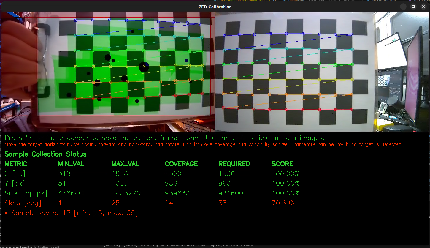
For each metric, the GUI shows the following information in a table:
- MIN_VAL: Minimum value stored in all the samples collected so far.
- MAX_VAL: Maximum value stored in all the samples collected so far.
- COVERAGE: The difference between the MIN_VAL and MAX_VAL, representing the range of variation in the collected samples.
- REQUIRED: The minimum required value for the COVERAGE to consider the metric as satisfied.
- SCORE: The percentage score for the metric, calculated as (COVERAGE / REQUIRED) * 100%.
You can follow the steps of the calibration process in the terminal output:
- The left camera is calibrated first, followed by the right camera to obtain the intrinsic parameters.
- Finally, the stereo calibration is performed to compute the extrinsic parameters between the two cameras.
Good calibration results typically yield a reprojection error below 0.5 pixels for each calibration step.
If any reprojection error is too high, the calibration is not accurate enough and should be redone. Before recalibrating, verify the following:
- The checkerboard is perfectly flat and securely mounted.
- The checkerboard is well-lit with even, stable lighting.
- Camera lenses are clean and free of smudges or dust.
- No reflections or glare appear on the checkerboard surface.
After a good calibration is complete, two files are generated:
zed_calibration_<serial_number>.yml: Contains intrinsic and extrinsic parameters for the stereo camera setup in OpenCV format.SN<serial_number>.conf: Contains the calibration parameters in ZED SDK format.
You can use these files in your ZED SDK applications:
-
Manually copy the
SN<serial_number>.conffile to the ZED SDK calibration folder to make the ZED SDK automatically use it:- Linux:
/usr/local/zed/settings/ - Windows:
C:\ProgramData\StereoLabs\settings
- Linux:
When calibrating a virtual ZED X One stereo rig, the serial number of the Virtual Stereo Camera is generated by the ZED SDK using the serial numbers of the two individual cameras. Make sure to use this generated serial number when loading the calibration in your application to have a unique identifier for the virtual stereo setup.
Use the Custom Stereo rig with the ZED SDK
Use the ZED SDK “virtual stereo” API functions (Recommended - For ZED SDK >= v5.1)
The ZED SDK version 5.1 and later includes built-in support for data acquisition from dual ZED X One stereo systems, allowing you to open and manage the virtual stereo rig directly through the SDK without relying on the ZED Media Server tool.
It is important that the two ZED X One cameras are properly connected and recognized by the system. You can verify this by using the command ZED_Explorer --all or the command ZED_Studio --list.
The ZED SDK requires a valid calibration file for the stereo system to compute depth information accurately. You can follow the calibration procedure to generate this file.
To open the dual ZED X One stereo system, you need to specify the serial numbers or the camera IDs of both cameras in the InitParameters when initializing the sl::Camera object:
Using camera serial numbers:
Using camera IDs:
You can use any custom serial numbers in the range [110000000,119999999], but we recommend using the serial number generated from the two ZED X One cameras using the function sl::generateVirtualStereoSerialNumber to avoid conflicts with existing devices.
Use the ZED Media Server tool (Obsolete - For ZED SDK < v5.1)
The first step is to configure a virtual stereo camera from two ZED X One cameras. Open the ZED Media Server tool to set up this system.
At the time of writing this documentation, some ZED SDK Tools (e.g, ZED Depth Viewer, ZEDfu) do not support the new virtual stereo API. In this case, you need to use the ZED Media Server tool to create a virtual stereo camera from the two ZED X One cameras to use them with the custom stereo rig.
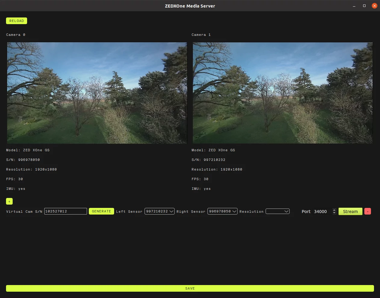
The ZED Media Server GUI lets you set up which camera should be the left and which should be the right, using the cameras’ serial numbers. Please make sure that the system is correctly set up, especially that the left and right cameras are not swapped.
Set the desired resolution, then click the SAVE button at the bottom once the system is set up. This stores the configuration of the cameras’ serial numbers and their location in the virtual stereo system. The virtual camera serial number (SN) on the left is the one used in the ZED SDK to reference this virtual stereo camera.
Click the Stream button to start streaming the images.
The GUI can be closed; a service (zed_media_server_cli) will automatically start in the background to stream data from the virtual stereo camera.
There is no restriction on the virtual camera setup, which allows for a ZED X One to be used in multiple virtual stereo cameras at once.
Please note that at this point the stereo camera images are available but require a calibration procedure to be usable. The calibration provides the ZED X One cameras’ relative position to each other (known as extrinsic parameters) and can also refine or compute their lens parameters, such as focal length, optical center, and distortion (known as intrinsic parameters). These calibration parameters are used by the ZED SDK to compute depth information.
The ZED X One stereo system can be opened with the ZED SDK by using the streaming input mode, on the same machine or remotely on a local network. The images are encoded and sent by the ZED Media Server tool (either by the GUI or the service).
To open a ZED X One stereo system, use the streaming address of the Jetson™ (127.0.0.1 for localhost) and the streaming port, typically 34000, in InitParameters.
Then, call open() to open the camera from the stream and grab() to grab a new frame and perform any type of processing.
Example Applications
The ZED SDK GitHub repository includes several example applications demonstrating how to use a dual ZED X One stereo system.
Use the Custom Stereo rig with ROS 2
The ZED ROS 2 wrapper supports dual ZED X One stereo systems.
When launching the ZED ROS 2 node, set virtual as the camera model and specify the serial numbers or camera IDs of both ZED X One cameras in the launch file parameters. For example:
or
For more details, refer to the ZED ROS 2 wrapper documentation.